OSPF is a link-state routing protocol that was developed as an alternative for the distance vector Routing Information Protocol (RIP). OSPF has significant advantages over RIP in that it offers faster convergence and scales to much larger network implementations.
OSPF has the concept of Areas that identifies a “domain” in which the routers can exchange packets (or certain type of packets). A link is an interface on a router or a network segment that connects 2 routers. Routers running OSPF can exchange five type of packets (Link-State Packet or LSP):
- Hello Packet: used to discover neighbors and build adjacencies between them
- Database Description Packets (DBD): Checks for database synchronization between routers
- Link-State request Packets (LSR): Requests specific link-state records from router to router
- Link-State Update Packets (LSU): Sends specifically requested link-state records
- Link-State acknowledgment Packet (LSA): Acknowledges the other packet types
The OSPF that runs an OSPF Process mantains 3 databases:
Adjacency Database (Neighbor Table): this can be viewed with the show ip ospf neighbor
R1#sh ip ospf neighbor

Neighbor ID     Pri   State           Dead Time   Address         Interface
2.2.2.2           1   FULL/BDR        00:00:38    192.168.1.2     GigabitEthernet0/1
3.3.3.3           1   FULL/DR         00:00:37    192.168.1.3     GigabitEthernet0/1
Link-state Database (LSDB) (Topology Table): this can be viewed with the show ip ospf database
R1#show ip ospf database

            OSPF Router with ID (1.1.1.1) (Process ID 1)

                Router Link States (Area 0)

Link ID         ADV Router      Age         Seq#       Checksum Link count
1.1.1.1         1.1.1.1         99          0x80000003 0x0098B7 1
2.2.2.2         2.2.2.2         90          0x80000006 0x0054EF 1
3.3.3.3         3.3.3.3         91          0x80000005 0x001824 1

                Net Link States (Area 0)

Link ID         ADV Router      Age         Seq#       Checksum
192.168.1.3     3.3.3.3         100         0x80000002 0x008D16
Forwarding Database (Routing Table): this can be viewed with the show ip route
R1#show ip route
Codes: L - local, C - connected, S - static, R - RIP, M - mobile, B - BGP
       D - EIGRP, EX - EIGRP external, O - OSPF, IA - OSPF inter area
       N1 - OSPF NSSA external type 1, N2 - OSPF NSSA external type 2
       E1 - OSPF external type 1, E2 - OSPF external type 2
       i - IS-IS, su - IS-IS summary, L1 - IS-IS level-1, L2 - IS-IS level-2
       ia - IS-IS inter area, * - candidate default, U - per-user static route
       o - ODR, P - periodic downloaded static route, H - NHRP, l - LISP
       a - application route
       + - replicated route, % - next hop override, p - overrides from PfR

Gateway of last resort is not set

      192.168.1.0/24 is variably subnetted, 2 subnets, 2 masks
C        192.168.1.0/24 is directly connected, GigabitEthernet0/1
L        192.168.1.1/32 is directly connected, GigabitEthernet0/1
How it works?
The router builds the topology table using results of calculations based on the Dijkstra shortest-path first (SPF) algorithm. The SPF algorithm is based on the cumulative cost to reach a destination. The SPF algorithm creates an SPF tree by placing each router at the root of the tree and calculating the shortest path to each node. The SPF tree is then used to calculate the best routes. OSPF places the best routes into the forwarding database, which is used to make the routing table. As said before to make OSPF more efficient and scalable it supports hierarchical routing using areas. An OSPF area is a group of routers that share the same link-state information in their LSDBs. OSPF can be implemented in one of two ways, as follows:
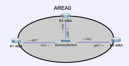
Single-Area OSPF: Only 1 Backbone Area (usually Area 0) where all the routers can exchange packets and routes
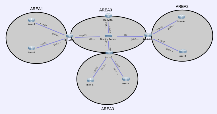
Multiarea OSPF: Multiple areas connected to a backbone Area0 by ABR (Area Border Router) or ASBR (Autonomous System Border Router)
OSPF Operation
When OSPF is enabled on the interface the router transitions from a Down state to the Init state and starts to send Hellos in attempt to discover neighbors. When a neighbor router receives and hello it add the neighbor router to his neighbor list and respond with another Hello containing its own router ID. At this point the 2 routers can exchange Hello packets and they transition to the 2-Way State and the next state depends on the type of network configured on the interfaces. If the routers are on a Point-to-Point link the next state is the ExStart where they will start with the exchange of the DBD packet. They will establish a Master-Slave association in which only the Master can change the Sequence Number of the DBD packet. If the network type is a Multiaccess Network (NBMA) or a Broadcast Multiaccess Network then the DR/BDR Election occur. The Next state is Exchange State where there is the real exchange of the DBD packets. If more information on the routes are needed the routers transition to the Loading State otherwise they will reach a Full State where the database are fully synchronized. So to summirize:
- Down
- Init State
- 2-Way State
- ExStart State
- Exchange
- Loading
- Full
Type of Networks
There are mainly 3 type of network for OSPF:
- Point-to-Point Networks
- Broadcast (Multiaccess) Networks
- Non-broadcast (Multiaccess) Networks (NBMA or Point-to-Multipoint)
The type of network is critical for OSPF because it allow OSPF to behave differently based on this.
The first one (Point-to-Point Network) is the simplest and we only have 2 OSPF routers on the link. There is no need for a DR/BDR election since the hello packets can be exchanged only between these 2 routers and they will be sent to the Multicast address 224.0.0.5
The Broascast (Multiaccess) Network is a network that supports multiaccess and broadcast communications meaning that and hello packet could be sent to multiple/all routers. This type of network require a DR/DR Election to control the hello packets exchange and the routers will only establish a Full Adjacency with the DR/BDR. All the other (DOTHER) will only reach the 2-Way state. The Hello packets are sent to the 224.0.0.6 address (All DR-Routers).
The Non-Broadcast Multiaccess Networks (NBMA) network support multiaccess but doesn’t support broadcast communications. In modern networks, DMVPN is example of Non-Broadcast multiaccess networks (in old networks Frame-Relay was an NBMA). Given this limitation the routers in this type of network needs to establish a full mesh and it requires a DR/BDR election but since broadcast is not supported the neighbors needs to be manually configured.
The Point-to-Multipoint networks is ideal for network segments that do not provide full mutual connectivity between the attached routers. The main characteristics of this network type are that Multicast can still be used to discover neighbors but there’s not DR/BDR election.
The command show ip interface will show the type network configured on the interface.
GigabitEthernet0/1 is up, line protocol is up
  Internet Address 192.168.1.1/24, Area 0, Attached via Network Statement
  Process ID 1, Router ID 1.1.1.1, Network Type BROADCAST, Cost: 1
  [...]
R2#sh ip ospf interface
GigabitEthernet0/1 is up, line protocol is up
Internet Address 192.168.1.2/24, Area 0, Attached via Network Statement
Process ID 1, Router ID 2.2.2.2, Network Type POINT_TO_POINT, Cost: 1
[...]DR/BDR Election
The OSPF DR and BDR election is based on the following criteria, in sequential order:
- The routers in the network elect the router with the highest interface priority as the DR. The router with the second highest interface priority is becomes the BDR.
- The priority can be configured to be any number between 0 – 255.
- If the interface priority value is set to 0, that interface cannot be elected as DR nor BDR.
- The default priority of multiaccess broadcast interfaces is 1.
- If the interface priorities are equal, then the router with the highest router ID is elected the DR. The router with the second highest router ID is the BDR.
The election process takes place when the first router with an OSPF-enabled interface is active on the network. If all of the routers on the network have not finished booting, it is possible that a router with a lower router ID becomes the DR.
The addition of a new router does not initiate a new election process.
After the DR is elected, it remains the DR until one of the following events occurs:
- The DR fails.
- The OSPF process on the DR fails or is stopped.
- The multiaccess interface on the DR fails or is shutdown.
If the DR fails, the BDR is automatically promoted to DR. This is the case even if another DROTHER with a higher priority or router ID is added to the network after the initial DR/BDR election. However, after a BDR is promoted to DR, a new BDR election occurs and the DROTHER with the highest priority or router ID is elected as the new BDR.
OSPF Interface Priority
The ip ospf priority command set the router priority on a specific link which determines the designated router for that network. If the interface priorities are equal on all routers in the same segment, the router with the highest router ID is elected the DR. Instead of relying on the router ID, it is better to control the election by setting interface priorities. This also allows a router to be the DR in one network and a DROTHER in another. To set the priority of an interface, use the command ip ospf priority value, where value is 0 to 255. A value of 0 means that the router won’t partecipate in the DR/BDR election process.
OSPF Metric
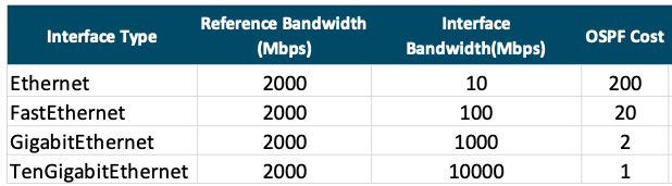
Routing protocols use a metric to determine the best path of a packet across a network. OSPF uses cost as a metric. A lower cost indicates a better path. The Cisco cost of an interface is inversely proportional to the bandwidth of the interface. Therefore, a higher bandwidth indicates a lower cost. The formula used to calculate the OSPF cost is:
Cost = reference bandwidth / interface bandwidth
The default reference bandwidth is 108 (100,000,000); therefore, the formula is:
Cost = 100,000,000 bps / interface bandwidth in bps
Because the OSPF cost value must be an integer, FastEthernet, Gigabit Ethernet, and 10 GigE interfaces share the same cost. To correct this situation the auto-cost reference-bandwidth command can be used or it can be manually set using the ip ospf cost under the specific interface. For example we can use a reference bandwidth of 2000Mbps and the result will be like the table below: